|
Case Description (FSAR 2-D Model) |
2-Group Results |
8-Group Results |
|
Reference keff (all blades out) |
1.02491 |
1.02432 |
|
Total worth of Blade 1 |
3.00 |
3.00 |
|
Total worth of Reg. Rod in D8 |
0.58 |
0.55 |
Summary of Work for April 1999 (Project #14-08239-F)
Computational Support for the HEU to LEU Conversion of the UMLRR
Dr. John R. White
Two major tasks were addressed as part of this project during April 1999:
I. Development of an 8-group cross section library for use with VENTURE, and
II. Selection of a new reference LEU configuration that retains the regulating rod in its current D9 location.
Each task is described in some detail in the remainder of this progress report.
Task I -- 8-Group Library for VENTURE
Core physics computations for thermal reactors are often accomplished with effective 2-group cross sections within the diffusion theory approximation to neutron transport. Locally we use the VENTURE code to accomplish these calculations. The 2-group approximation leads to relatively efficient calculations and it gives a reasonable representation of the energy spectrum for the computation of reactivity effects and power distributions within thermal systems. When more detailed knowledge of the energy spectrum is required -- for the design or analysis of experimental facilities, for example -- a multigroup library is needed, and this is often used with the transport theory approximation to the neutron balance equation. At UMass-Lowell we use the 2-D DORT code for these kinds of analyses, and a coupled neutron-gamma multigroup library with 47 neutron groups and 20 gamma groups has already been prepared for use with DORT (see Ref. 1 for further details).
However, at present, a DORT model of the proposed LEU-fuelled UMLRR is not available. Thus, it would be convenient to have some intermediate multigroup capability within the existing VENTURE models for rough estimates of the energy spectra in various facilities. Also, with the development of 3-D modeling capability within VENTURE (see the March 1999 Progress Report), this multigroup capability could also be quite useful for rough spectrum calculations in 3-D geometries.
With the above motivation, a new 8-group neutron cross section library was developed for use within both VENTURE and DORT. An outline of the cross section development procedure used in this work is given in Ref. 1. For the 8-group library, only the final XSDRN 1-D core calculation was repeated, but this time the 199-group space-dependent neutron fluxes were used to collapse the fine-group cross sections into eight energy bins. The group structure used is given in Table I, and it shows a roughly equal-lethargy broad-group structure (except for the lowest group). The average fission spectrum obtained from the XSDRN calculations is also tabulated here. The final 8-group ANISN-formatted libraries from the XSDRN runs are stored as leu8gvxs.asnlib and leu8gdxs.asnlib, respectively, for use with subsequent 8-group VENTURE and DORT computations.
Table I Energy group structure for the 8-group library.
|
Group # |
Upper Energy (eV) |
Lethargy |
Change in Lethargy |
Fission Spectrum |
|
1 |
1.964e+7 |
0.018 |
2.98 |
0.7028 |
|
2 |
1.003e+6 |
2.993 |
2.20 |
0.2830 |
|
3 |
1.111e+5 |
5.193 |
2.35 |
0.0138 |
|
4 |
1.060e+4 |
7.543 |
2.15 |
0.0004 |
|
5 |
1.234e+3 |
9.693 |
2.50 |
0.0000 |
|
6 |
1.013e+2 |
12.19 |
2.25 |
0.0000 |
|
7 |
1.068e+1 |
14.44 |
2.37 |
0.0000 |
|
8 |
1.000e+0 |
16.81 |
11.5 |
0.0000 |
|
9 |
1.000e-5 |
28.32 |
----- |
----- |
The leu8gvxs.asnlib 8-group ANSIN-formatted library was put into final GRUPXS format for use with VENTURE. This 8-group library is referenced by VENTURE as the umlleu8g.gru file and the original 2-group library is accessed as the umlleu2g.gru library. A preliminary test of the new VENTURE 8-group dataset was conducted by simply comparing some key core physics parameters for a few 2-D configurations with previous 2-group calculations. Summary keff and reactivity worth results from these calculations are shown in Table II.
These comparisons all look quite reasonable. The 8-group and 2-group keff results are well within the expected uncertainty range and the blade worth calculations are also very comparable. Thus, it appears that the 8-group library is functional and ready for routine use.
Table II Comparison of 2-group versus 8-group keff and worth calculations.
|
Case Description (FSAR 2-D Model) |
2-Group Results |
8-Group Results |
|
Reference keff (all blades out) |
1.02491 |
1.02432 |
|
Total worth of Blade 1 |
3.00 |
3.00 |
|
Total worth of Reg. Rod in D8 |
0.58 |
0.55 |
Task II -- Selection of a New Reference LEU Core Configuration
The February 1999 Progress Report discussed some computations that tried to estimate the worth of the regulating rod (RR) in the new LEU-fuelled core. The reference configuration, referred to as the reference FSAR model, has the regulating blade moved from its current D9 location (in the HEU core) to the D8 position for the LEU core. This decision was made nearly 10 years ago when the original HEU to LEU conversion calculations were made. However, the current management of the facility feels that the plan for moving the RR from D9 to D8 could be difficult to implement and could lead to subsequent problems. But, the 20-element relatively small reference configuration described in the FSAR supplement leads to a relatively low RR worth when the current D9 position is used. Thus, if the RR is to remain in position D9, an alternative reference LEU core configuration will be required.
------------------------
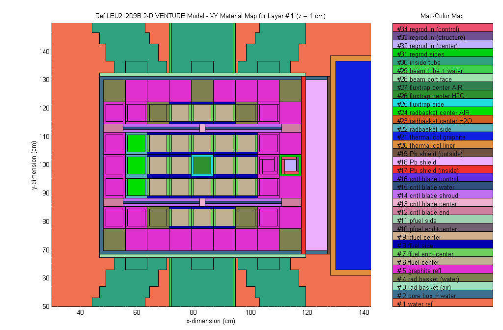
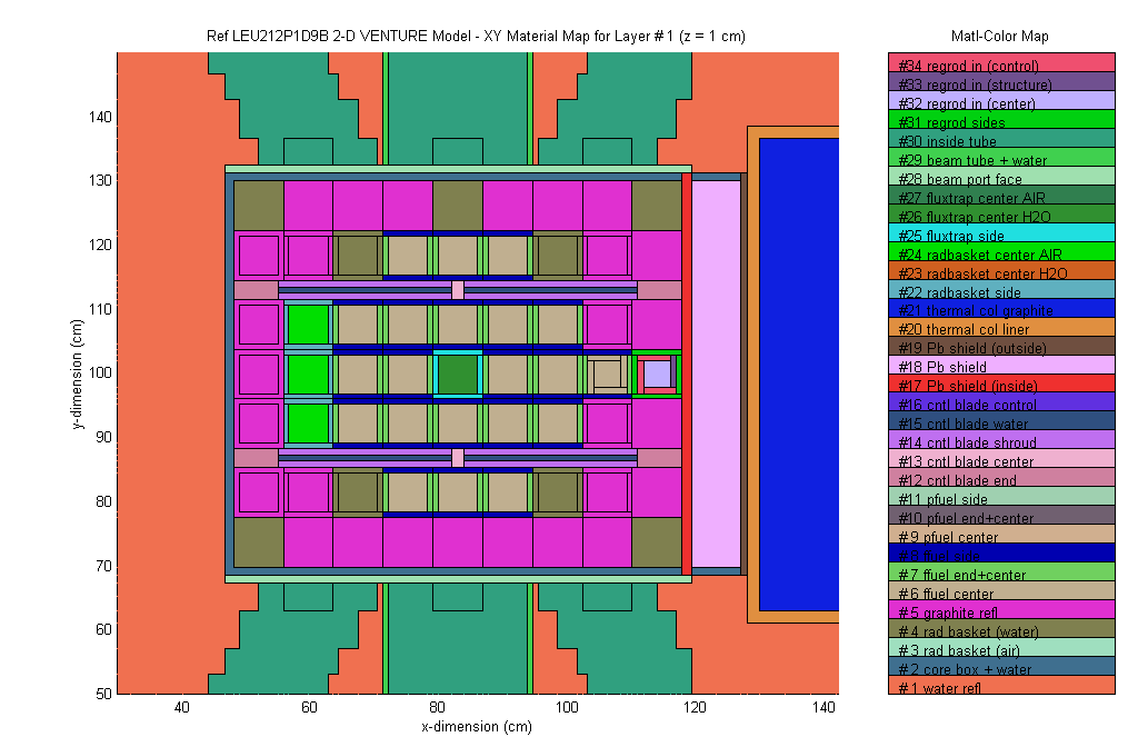
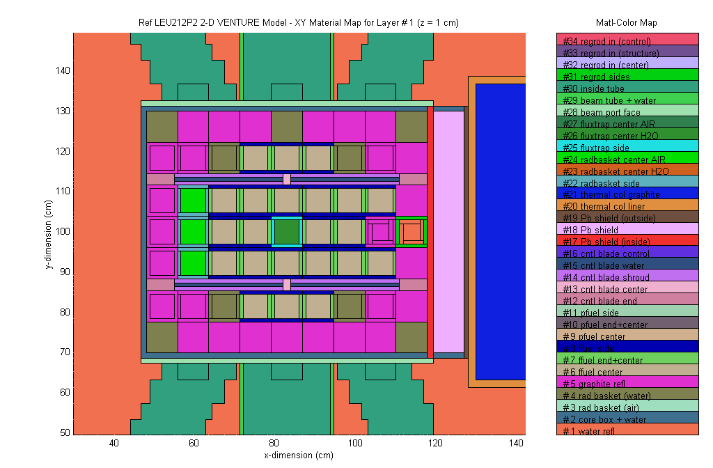
Note: The February 1999 Progress Report tabulated some worths with the RR in the D9 versus D8 position. For the calculations with the RR in the D9 location, a graphite reflector was placed in D8 and two radiation baskets were in C8 and E8. The original intent of these calculations, however, was to have a graphite reflector in all three locations (C8, D8, and E8), which would lead to a higher RR worth. Thus, the February 1999 results are definitely misleading, and corrected values are given below (see results for the leu212, leu212d9a and leu212d9b cases).
------------------------
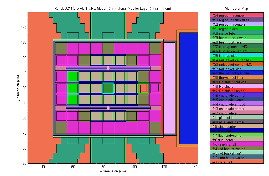
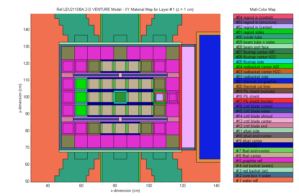
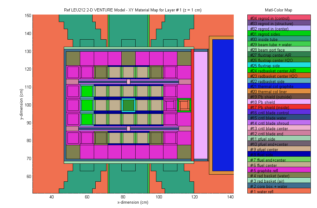
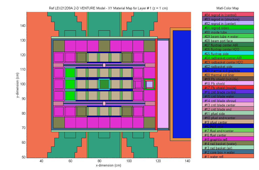
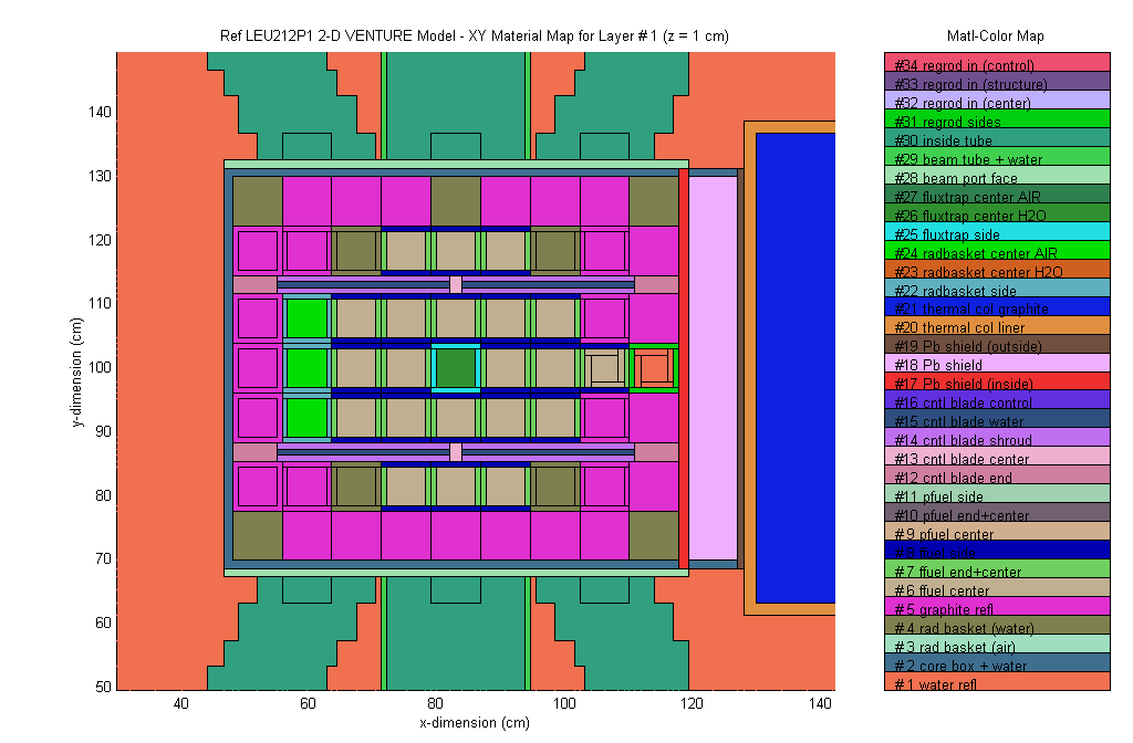
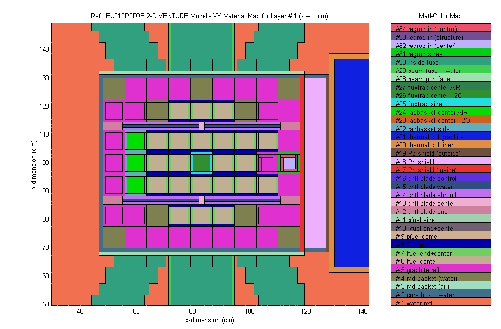
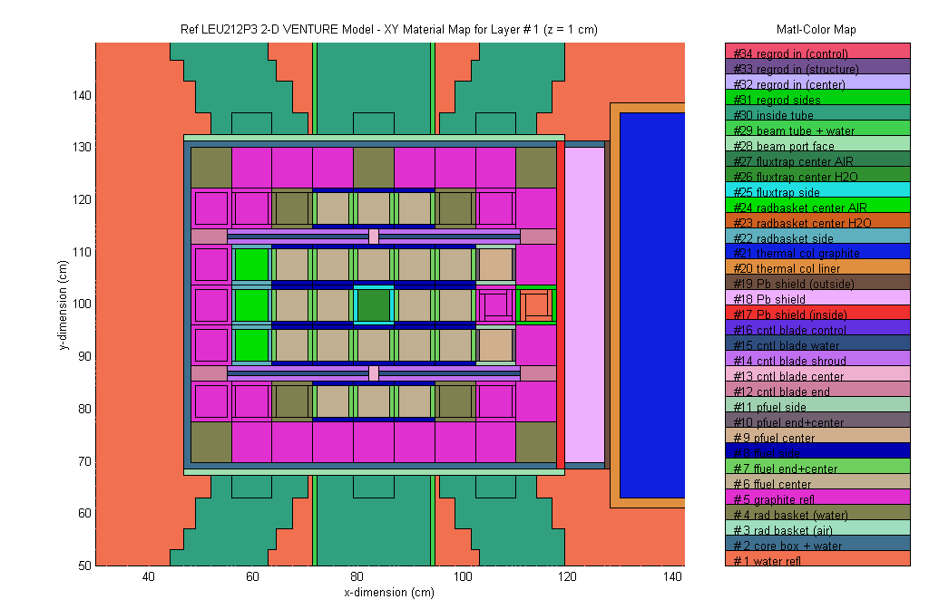
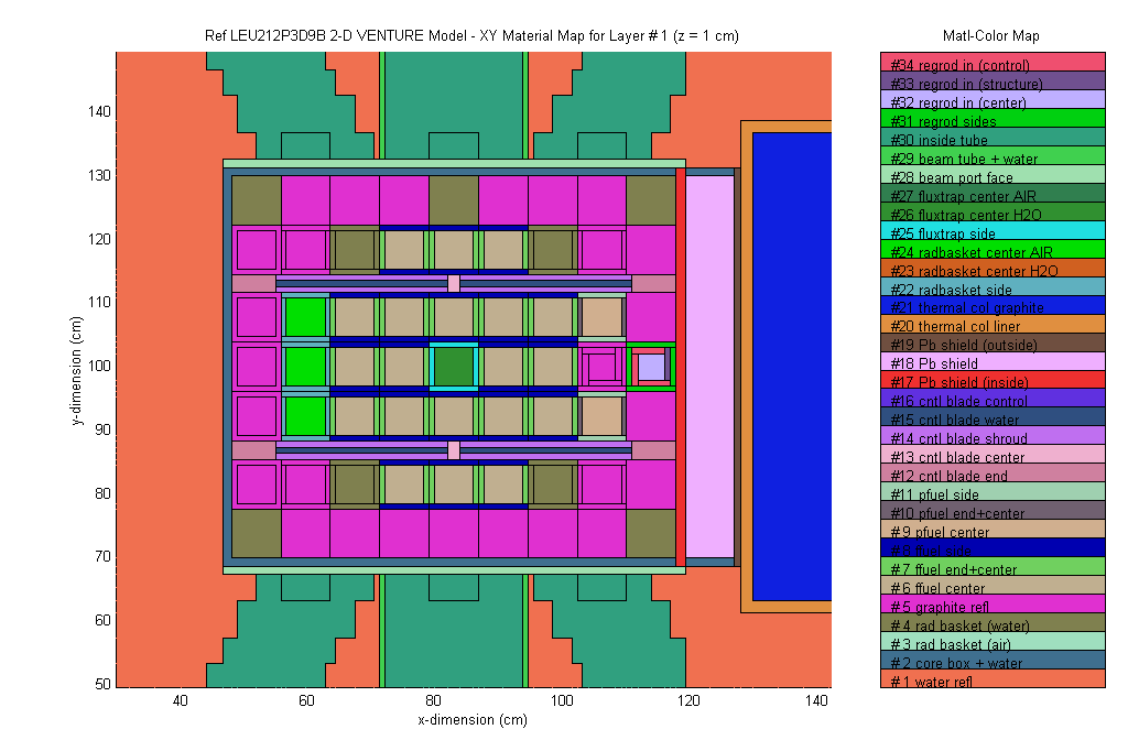
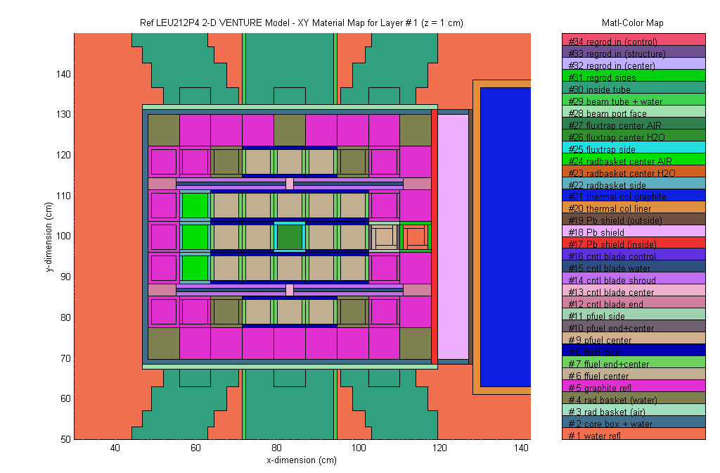
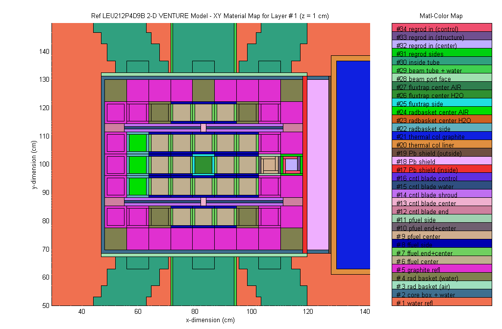
With the above background to set the proper context, a series of 2-D XY VENTURE calculations were made to identify promising configurations that would lead to higher regulating rod worths with the RR in position D9. Summary results from these calculations are given in Table III. The FSAR reference model and regulating rod (RR) worth calculations are given as the first two entries (leu211 and leu211d8a cases), where the RR is located in the D8 position. All the other models have the RR in D9, with various combinations of full or partial fuel assemblies and graphite elements in grid positions C8, D8, and E8. All other grid locations are identical with those in the reference leu211 case.
Table III Summary results for several candidate reference configurations.
|
Case Description |
Case ID |
keff |
worth |
|
Reference case with RR in D8 (all blades out) |
leu211 |
1.02491 |
--- |
|
Worth of RR in D8 (away from core) |
leu211d8a |
1.01895 |
0.58 |
|
Graphite in C8, D8, and E8 (D9 RR out) |
leu212 |
1.03203 |
--- |
|
Worth of RR in D9 (away from core) |
leu212d9a |
1.02985 |
0.21 |
|
Worth of RR in D9 (facing towards core) |
leu212d9b |
1.02906 |
0.29 |
|
Full fuel in D8 & graphite in C8+E8 (D9 RR out) |
leu212p1 |
1.03979 |
--- |
|
Worth of RR in D9 (facing towards core) |
leu212p1d9b |
1.03553 |
0.41 |
|
Graphite in D8 & full fuel in C8+E8 (D9 RR out) |
leu212p2 |
1.04554 |
--- |
|
Worth of RR in D9 (facing towards core) |
leu212p2d9b |
1.04032 |
0.50 |
|
Graphite in D8 & partial fuel in C8+E8 (D9 RR out) |
leu212p3 |
1.03963 |
--- |
|
Worth of RR in D9 (facing towards core) |
leu212p3d9b |
1.03566 |
0.38 |
|
Partial fuel in D8 & graphite in C8+E8 (D9 RR out) |
leu212p4 |
1.03645 |
--- |
|
Worth of RR in D9 (facing towards core) |
leu212p4d9b |
1.03311 |
0.32 |
One problem with simply adding fuel into locations C8 - E8 to increase the RR worth in D9 is the increase in overall excess reactivity of the beginning-of-life (BOL) core. The goal here is to limit the computed k-excess to about 4![]() . Since the LEU fuel in so reactive, we clearly want to minimize the number of additional fuel assemblies added to the reference 20-element core (i.e. the leu211 case). Thus, the first variation that was investigated includes only graphite in the C8 - E8 positions (see the leu212 cases). This case had no increase in the fuel loading, but a net increase of about 0.7 % excess reactivity was observed because of the increased worth of graphite versus water reflection. The best RR worth for this configuration with the boral facing the core is about 0.29
. Since the LEU fuel in so reactive, we clearly want to minimize the number of additional fuel assemblies added to the reference 20-element core (i.e. the leu211 case). Thus, the first variation that was investigated includes only graphite in the C8 - E8 positions (see the leu212 cases). This case had no increase in the fuel loading, but a net increase of about 0.7 % excess reactivity was observed because of the increased worth of graphite versus water reflection. The best RR worth for this configuration with the boral facing the core is about 0.29![]() . Since the computed RR worths are expected to be a little high because of the modeling approximations that were required, this value is clearly too low for effective operation of the facility -- we really would like the computed RR worth to be greater than 0.35
. Since the computed RR worths are expected to be a little high because of the modeling approximations that were required, this value is clearly too low for effective operation of the facility -- we really would like the computed RR worth to be greater than 0.35![]() .
.
With the goal of increasing the RR worth, several combinations of full or partial fuel elements and graphite reflectors within grid positions C8 - E8 were attempted, with summary results also given in Table III. The best arrangement of the configurations tested was the leu212p1 sequence, where the computed keff is just about 1.40 and the calculated RR worth is 0.41![]() . Both these values meet the design goals, but the k-excess is at the upper limit and the RR worth is not far from its lower limit of 0.35
. Both these values meet the design goals, but the k-excess is at the upper limit and the RR worth is not far from its lower limit of 0.35![]() . However, this configuration appears feasible and it is a prime candidate for the new reference initial LEU core configuration with the RR in the D9 position. This candidate 2-D model represents a 21-element core that meets the design criteria imposed upon the system.
. However, this configuration appears feasible and it is a prime candidate for the new reference initial LEU core configuration with the RR in the D9 position. This candidate 2-D model represents a 21-element core that meets the design criteria imposed upon the system.
At this point, a brief discussion about uncertainty is needed. Clearly, there is inherent uncertainty in all the computations performed for the new LEU core. As a particular example, the 3-D results reported in the March 1999 Progress Report showed a 1.8![]() increase in keff for the 3-D models relative to the 2-D computations. This is significant, and it emphasizes the need for flexibility in the design to account for uncertainty in the mathematical modeling of complex nuclear systems. In reality, a more probable expectation is for the measured k-excess to be somewhere between the 2-D and 3-D computed values. However, the real core reactivity will not be known until actual measurements are made during the startup tests on the as-built LEU system. If the measured reactivity is lower that desired, one can simply replace some water reflectors with graphite reflectors to increase the actual core reactivity -- this is an easy fix. If, on the other hand, the core reactivity is too large, modifications in the initial configuration will be required that decreases k-excess, without adversely affecting the RR worth -- finding a fix here is not so easy.
increase in keff for the 3-D models relative to the 2-D computations. This is significant, and it emphasizes the need for flexibility in the design to account for uncertainty in the mathematical modeling of complex nuclear systems. In reality, a more probable expectation is for the measured k-excess to be somewhere between the 2-D and 3-D computed values. However, the real core reactivity will not be known until actual measurements are made during the startup tests on the as-built LEU system. If the measured reactivity is lower that desired, one can simply replace some water reflectors with graphite reflectors to increase the actual core reactivity -- this is an easy fix. If, on the other hand, the core reactivity is too large, modifications in the initial configuration will be required that decreases k-excess, without adversely affecting the RR worth -- finding a fix here is not so easy.
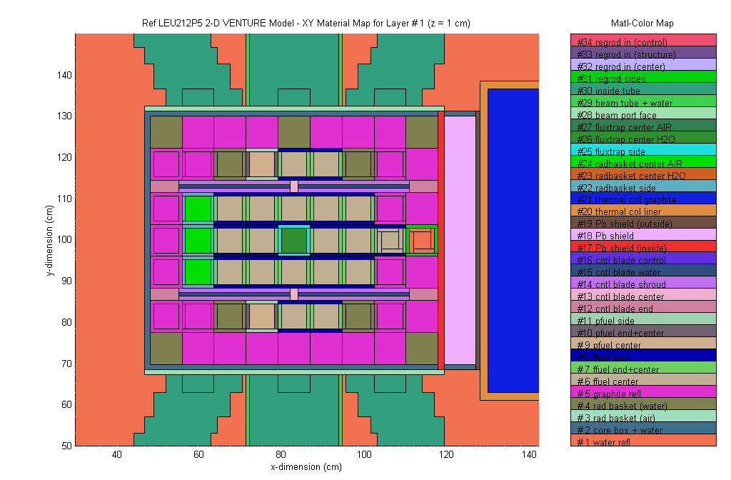
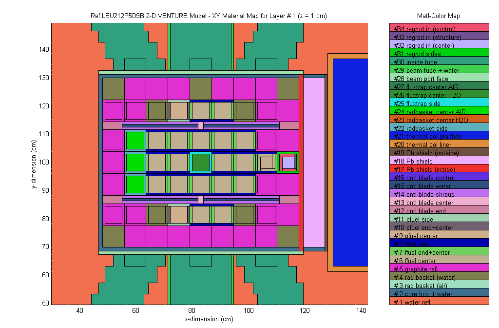
Since this latter situation is more troublesome, the selection process for a new reference LEU core configuration should definitely anticipate a low predicted core reactivity (i.e. a high measured value). Since the leu212p1 configuration is near the upper k-excess design limit, one possible configuration change is to replace the full fuel assemblies in the B4 and F4 grid locations with partial fuel elements. This should lower core reactivity and possibly even enhance the RR worth slightly. To test this hypothesis, a final set of 2-D XY computations, referred to as the leu212p5 cases, was made for this proposed configuration. Summary results for this configuration relative to the leu212p1 model are given in Table IV, and they clearly confirm expected trends. The leu212p5 configuration has a much lower k-excess, about 3.2![]() versus 4.0
versus 4.0![]() for the leu212p1 case, and it also has a slightly higher computed RR worth of 0.44
for the leu212p1 case, and it also has a slightly higher computed RR worth of 0.44![]() . Thus, this appears to be a better candidate design since it meets both reactivity design criteria (k-excess and RR worth) and it is more tolerant to modeling uncertainties relative to the leu212p1 model.
. Thus, this appears to be a better candidate design since it meets both reactivity design criteria (k-excess and RR worth) and it is more tolerant to modeling uncertainties relative to the leu212p1 model.
Table IV Comparison of the leu212p1 and leu212p5 designs.
|
Case Description |
Case ID |
keff |
worth |
|
Full fuel in D8 & graphite in C8+E8 (D9 RR out) |
leu212p1 |
1.03979 |
--- |
|
Worth of RR in D9 (facing towards core) |
leu212p1d9b |
1.03553 |
0.41 |
|
leu212p1 with partial fuel in B4+F4 (D9 RR out) |
leu212p5 |
1.03218 |
--- |
|
Worth of RR in D9 (facing towards core) |
leu212p5d9b |
1.02767 |
0.44 |
The above conclusion is only preliminary because final evaluation of this new configuration is not complete as yet -- a full set of blade worth and shutdown margin calcula-tions are needed and a consistent 3-D representation should be evaluated. However, this new configuration with 19 full fuel assemblies and 2 partial assemblies appears promising, and it represents the best candidate for a new reference core configuration at this time. Further evaluation and testing will be completed over the next several weeks, and a final decision concerning the new reference LEU initial loading will be made as soon as possible.
Although the selection of a final core configuration is still under study, it is clear from the above analyses that a suitable LEU configuration with the regulating rod in the D9 grid location can be found. Thus, one definitive conclusion from the current analysis can be made -- the regulating rod can indeed be left unaltered in the D9 grid position. It will need to be rotated so that the boral element is facing the core, but changing its grid location will not be required. How the core is configuration around this RR position still has some uncertainty, but the design analysis seems to be converging on the leu212p5 configuration. Additional analyses over the next few weeks should confirm this selection as the final reference LEU core layout.
References
1. J. R. White, "Cross Section Libraries and Preliminary Modeling for the Reference UMLRR LEU Core Configuration," Informal Documentation, UMass-Lowell (Jan. 1999).
